Extended Analysis of the General Two-mirror Dihedral (inter-mirror) Angle Case
By Philip Bradfield
Credentials
- MA (Cambridge: Physics), MSc (Aston), MInstP (UK), CPhys (UK)
- Fellow of the Higher Education Academy (UK), STEM Ambassador
- Retired University Senior Lecturer, Private Tutor: Math, Physics & Chemistry
Biography
- Retired academic scientist – still active
- Born at Derby (1942), and now retired to Dunfermline (near Edinburgh) Scotland.
- Taught Physics at Edinburgh, De Montford and Wolverhampton Universities and then (after a sabbatical MSc) Computer Science, also at Wolverhampton
- Research Interests: Optics, Solid-State Physics, Physical crystallography, Physics history and pedagogy
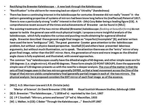
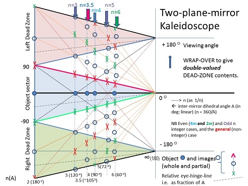
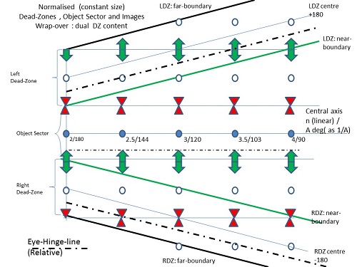
I have contributed a new extended analysis of the general two-mirror dihedral (inter-mirror) angle case, (ambiguity of final images) to an International Conference on the History of Physics ( Trinity College, Cambridge: Sept 2014) and to the BKS (USA).
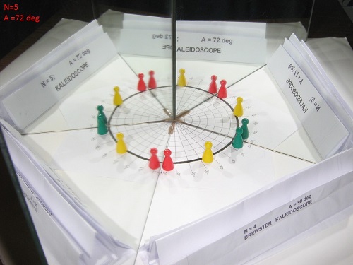
I use a simple polyangular (i.e. variable angle) two-mirror system to explore/demonstrate my results: there is one such from the early days, in the National Museum of Scotland (by Bate (London), c. 1820: designed by Brewster: cf. his 1817 Patent).
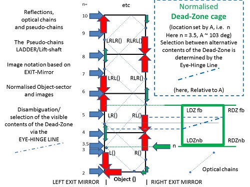
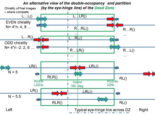
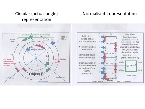
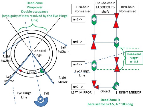
To demonstrate my results theoretically, I devised a full computer simulation: – the output showed the “ring” of images formed from any one (asymmetric) object (an irregular tetrahedron was used). The furthest images are “AMBIGUOUS” for a GENERAL dihedral angle – what you see depends on the choice of EXIT mirror. I used hatching/transparency to allow images “further in” to be seen even “through” the object for any given viewing direction.
I hope to gain some practical advice from you all, and am very happy to discuss theoretical/mathematical aspects. Feedback requested:
- I have constructed the classic three-mirror “triangular” truncated cone Kaleidoscope (1/48 of the total solid angle): with a mirrored “base” it yields convincing results: I use a simple asymmetric object in the K. i.e. 45, 35.3, 54.7 degree inter-edge angle tapering for the pairs of mirror-edges (tapering angles) cf. [001] ^ [011]; [011] ^ [111]; [111] ^ [001] crystallographic cubic system zone axes. The angles between the mirror-pairs (dihedral: largest angle between the two mirrors, i.e. “normally”) are 45, 90, 60 degrees (use a stereogram, as in crystallography: cubic symmetry). The images formed from any object point form “clusters” of the appropriate symmetry around the edges/joints: 8 (4mm), 6 (3m) and 4 (2mm).
- The other simple but “square” 3D truncated K (1/6 of the total solid angle) has four identical mirrors, each with tapering angle of 2*35.3 degree i.e. 70.6 degree. (cf. ANGLE BETWEEN [111] AND [-1 1 1] CRYSTALLOGRAPHIC CUBIC ZONE AXES) and the inter-mirror dihedral angles are all 120 degree.
- I believe this is often used in hands-on “Exploratorium” venues, using a suitable TV/PC monitor screen at the base of the broad truncated “square” cone.
- The simplest three-mirror K is of course three plane mirrors meeting normally: the classic “cube corner”: optically noted for its property of reflecting any incident light back along its original path, though transversely displaced unless directed at the unique central common point – this property best explored using a simple pencil to represent the incident beam (i.e. defined by any two points along the pencil). The object plus seven distinct images are useful in introducing the other 3D Ks: the even and odd chirality (handedness) of these images is clearly evident when an asymmetric object (e.g. hand) is used.